Flush-Frame Connections

Reduce steel weight up to 35% with performance equal to wide-flange beams

Flush-frame connections Missouri State University

Our published standards simplify specification and eliminate girder torsion concerns during erection.

Flush-frame connections reduce design time, coordination, and costs, while streamlining fabrication and erection

Steel joists with flush-frame connections offer significant weight savings compared to wide-flange beams while providing equivalent bolted connection, stiffness, and vibration performance.

Our published set of standards for flush-frame connections improves coordination between specifiers, joist manufacturers, steel fabricators, and erectors. This reduces design time, accelerates joist and wide-flange girder fabrication, and streamlines erection.

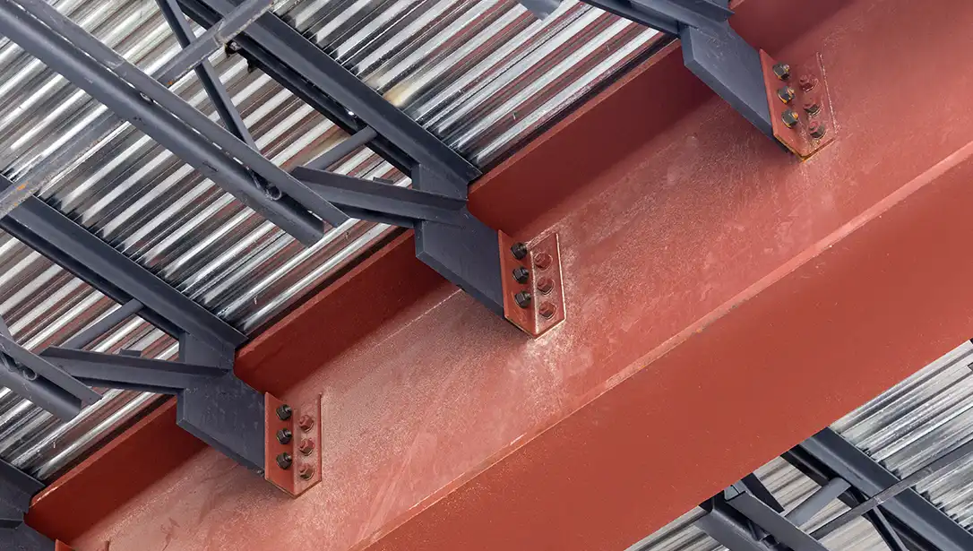
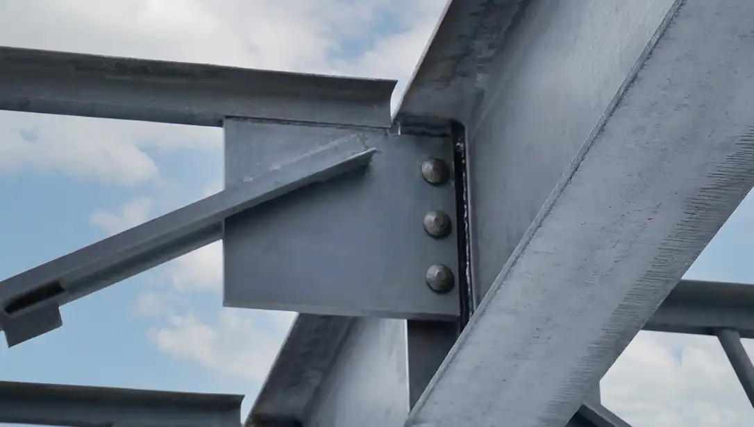
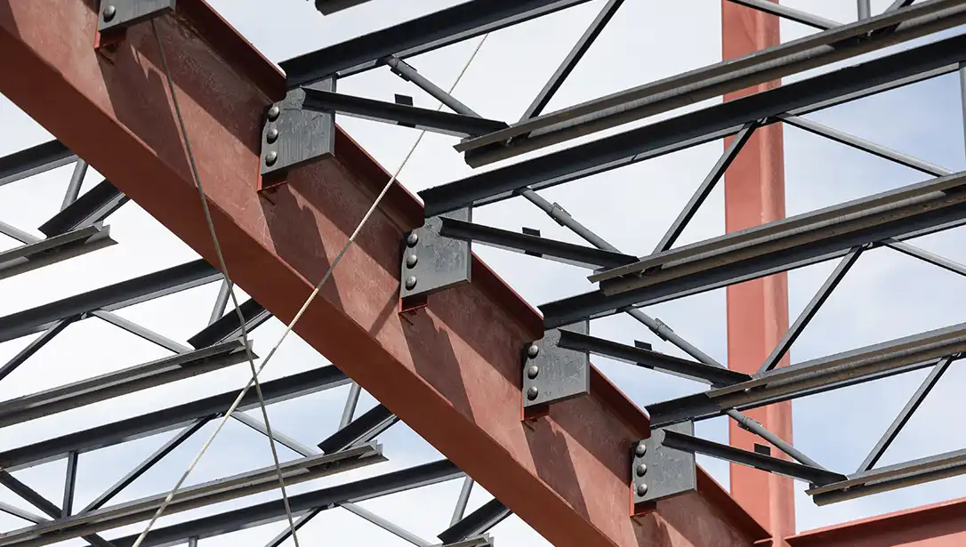
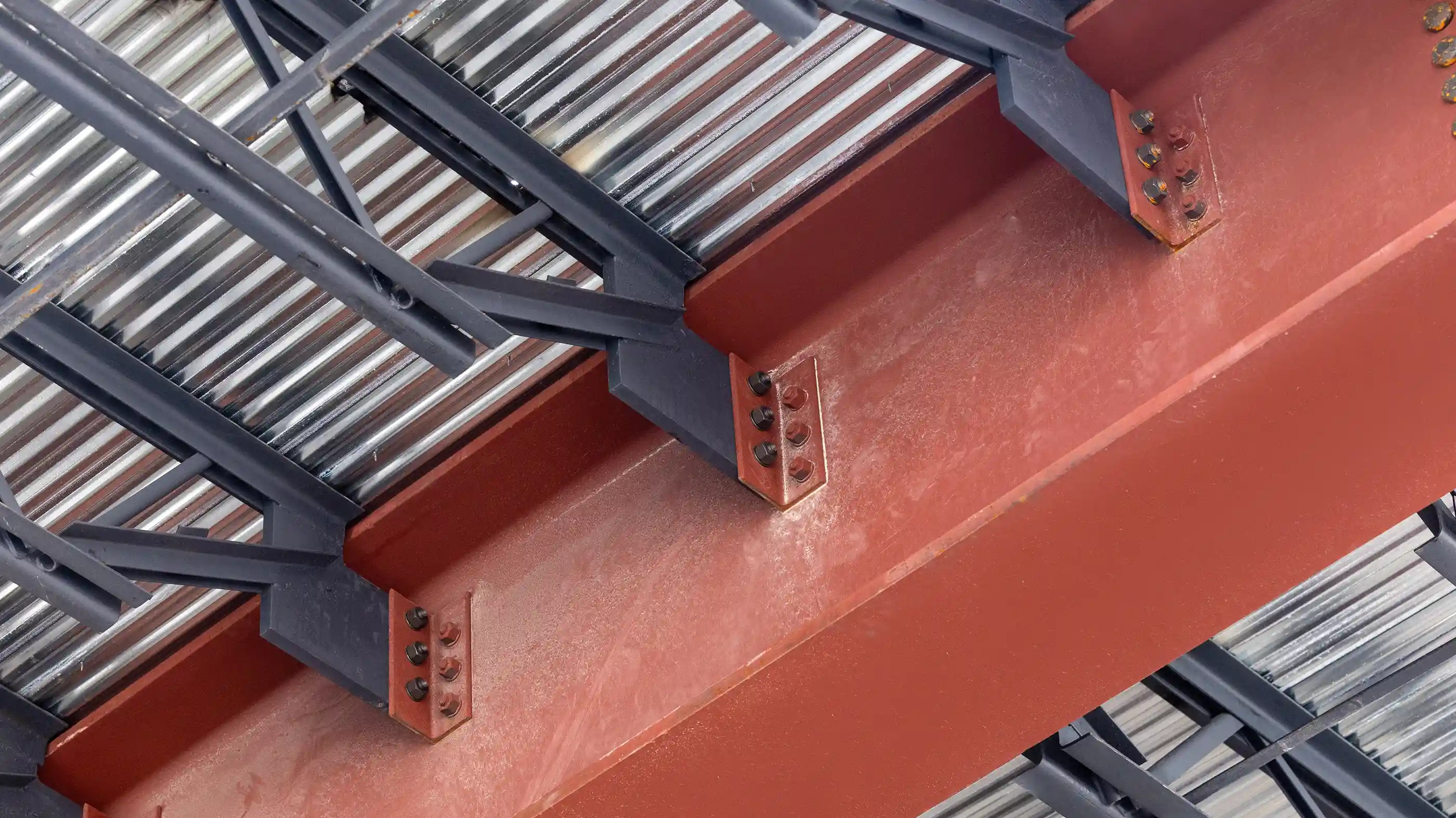
The difference is in our flush-frame connection design

Flush-frame connections from New Millennium feature a joist-reaction work point designed to occur at the centerline of the wide-flange girder. This eliminates girder torsion concerns during erection and/or due to final design loading of a perimeter wide-flange girder. Our published standards take advantage of this key design feature.

The project engineer of record (EOR) is solely responsible for the selection of appropriate connections between the joist and wide-flange girder. Our published standards may be used as-is or adapted by the project engineer of record (EOR) as appropriate to the specific project conditions.

Flush Frame Connections Diaphragm Drawings

Benefits of flush-frame connections by New Millenniumn

  • Enhanced floor vibration performance equivalent to wide-flange beams
  • Published standards simplify specification
  • Elimination of girder torsion concerns
  • Elimination of blocking between joist seats for diaphragm shear transfer
  • Bolted connections eliminate the field welding required for traditional joist seats.

How do steel joists outperform wide-flange beams?

  • Up to 35% reduction in weight lowers material and construction costs
  • Reduced floor-to-floor height with steel joist MEP integration
  • Joist camber built into the manufacturing process with no additional time or cost
Flush-frame steel joists and beam with deck
Flush-frame steel joist connection close up
Flush-frame steel joists to beam

Under-Flange (UF) Connections

Connection Number Max Girder Flange Width (in) Max Joist Vertical LRFD Reaction (kips) Number of Bolts Bolt Diameter (in) Bolt Grade ASTM Hole Diameter in Joist End Plate (in) Slot Width in Shear Tab (in) Slot Length in Shear Tab (in) Connection Drawing
NMUFC-1 11.50 62 3 1.00 A490-N 1.125 1.125 1.3125 NMUFC-1.pdf
NMUFC-1A 17.50 62 3 1.00 A490-N 1.125 1.125 1.3125 NMUFC-1A.pdf
NMUFC-2 11.50 97 4 1.00 A490-N 1.125 1.125 1.3125 NMUFC-2.pdf
NMUFC-2A 17.50 97 4 1.00 A490-N 1.125 1.125 1.3125 NMUFC-2A.pdf
NMUFC-3 11.50 145 4 1.25 A490-N 1.375 1.375 1.625 NMUFC-3.pdf
NMUFC-3A 17.50 145 4 1.25 A490-N 1.375 1.375 1.625 NMUFC-3A.pdf

Extended-Tab (ET) Connections

Connection Number Max Girder Flange Width (in) Max Joist Vertical LRFD Reaction (kips) Number of Bolts Bolt Diameter (in) Bolt Grade ASTM Hole Diameter in Joist End Plate (in) Slot Width in Shear Tab (in) Slot Length in Shear Tab (in) Connection Drawing
NMETC-1 11.50 26 3 1.00 A490-N 1.125 1.125 1.3125 NMETC-1.pdf
NMETC-2 11.50 47 4 1.00 A490-N 1.125 1.125 1.3125 NMETC-2.pdf
NMETC-2A 17.50 35 4 1.00 A490-N 1.125 1.125 1.3125 NMETC-2A.pdf
NMETC-3 11.50 90 4 1.25 A490-N 1.375 1.375 1.625 NMETC-3.pdf
NMETC-3A 17.50 65 4 1.25 A490-N 1.375 1.375 1.625 NMETC-3A.pdf
NMETC-4 11.50 114 5 1.25 A490-N 1.375 1.375 1.625 NMETC-4.pdf
NMETC-4A 17.50 100 5 1.25 A490-N 1.375 1.375 1.625 NMETC-4A.pdf
NMETC-5 11.50 136 6 1.25 A490-N 1.375 1.375 1.625 NMETC-5.pdf
NMETC-5A 17.50 136 6 1.25 A490-N 1.375 1.375 1.625 NMETC-5A.pdf
 

DESIGN RESPONSIBILITY NOTICE: Our published set of standards for flush-frame connections are provided as design aids to expedite the design and coordination of open-web steel joists with flush-framed connections to wide-flange girders. The project engineer of record (EOR) is solely responsible for the design of the structure, the specification of the joists, and the selection of appropriate connections between the joist and wide-flange girder. To that end, these details may be used as-is or adapted by the EOR as appropriate to the specific project conditions, including the size of the beam shear tab, size of bolts, grade of bolts, quantity of bolts, and weldment of beam tab plate to the wide-flange girder with appropriate weld size proportionate to the web thickness of the wide-flange girder. New Millennium provides design calculations for each standard connection detail for the EOR to use in validating strength and assessing appropriateness to the specific project. New Millennium is not responsible for verifying whether these connection designs are appropriate for use in any given condition on any given project.

Featured Projects